Impedance Controller on Emika Panda Arm
Overview
In modern robotics, developing seamless human-robot interactions is key to making robot more intuitive and easy for humans to adapt to using. This project focuses on implementing impedance control for an Franka Emika Panda Robot Arm to make it more compliant and easier to guide by hand. By designing an impedance model, the system can adjust how the robot responds to user input, enabling smooth and effortless movements
The Franka Emika Panda Robot Arm is known for its precision and advanced control features. The goal of this project is develop a impedance control system that minimizes user effort while keeping the arm stable and responsive. This involves fine-tuning the virtual mass, damping, and stiffness coefficients to balance flexibility and accuracy.
Through impedance control, this project aims to enhance the way people and robots work together, making it ideal for hands-on tasks like collaborative work. Check out this controller being used for data collection in this project.
Impendance Control Algorithm

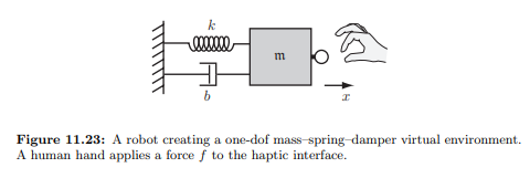
This project focuses on tuning the parameters in the second half of the equation which equate to fext. That equation is derived from a spring damper system, shown below.

The coefficients from the diagram and equation are defined as the following:
- x: task-space configuration of the robot
- M: virtual mass matrix
- B: virtual damping matrix
- K: virtual stiffness matrix
- fext: external force applied to the robot
In this project, parameters M, B, and K were tuned to achieve the deisred dynamic behavior of the robotic system. Some observations from the tuning:
- High stiffness (K) - reduces motion for a given applied force, resulting in rigid movements
- High damping (B) - smooths the motion to decrease any oscillations
- Low virtual mass (M) - increase the responsiveness to external forces
Implementation on Franka Robot
In partnership with Jihai Zhao, we implemented the impedance controller based on the C++ Libfranka library provided by Franka. We tested three different modes: damping mode, friction compensation mode, and white light mode (default). The damping mode consisted of adding an additional negative damper to increase the feeling of weightlessness when moving the robot. The friction compensation mode added a constant joint impedance to counteract the effects of friction in each joint.
Evaluate Mode Performance
We used the dynamics equation below to desicribe the force that the user applied at the end effector.
f(t) = m * a(t) - c * v(t)

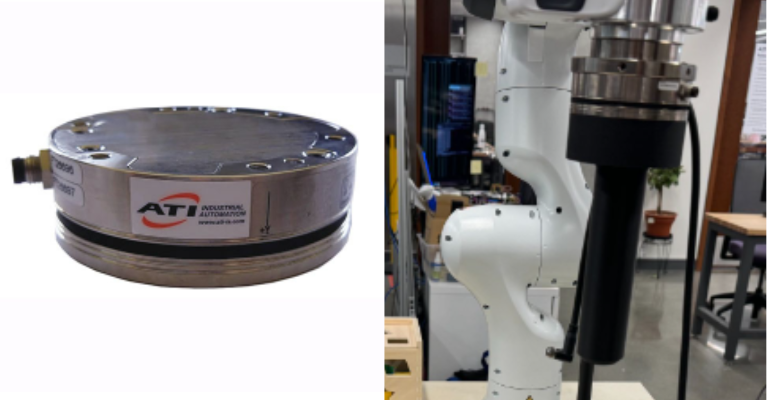
Using an Axia80-M8 force-torque sensor to measure the force and torque each user applied, we could back calculate the estimated m and c for each mode. Ideally, the best mode should have a relatively small m and c, stable performance in all directions, and close to equivalent m and c values. Based on those conditions, damping mode in performs the best.
| Condition | Axis | m | c |
|---|---|---|---|
| Damping | X | 0.09225413 | 2.62787636 |
| Y | 6.83681977 | -3.70447808 | |
| Z | 1.24047087 | 13.94127596 | |
| Friction Compensation | X | -3.21932284 | 1.68266821 |
| Y | 1.76315165 | 2.38112476 | |
| Z | 12.08837463 | 12.94580011 | |
| White Light | X | -8.55692881 | 3.82439509 |
| Y | 12.06393627 | 0.78625834 | |
| Z | 14.77014982 | 25.40289417 |